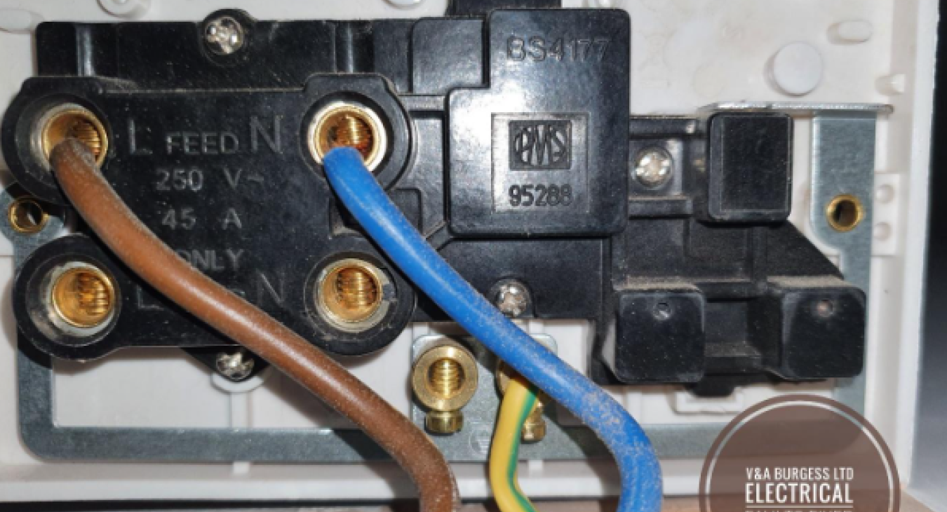
Load vs Line. What’s the difference between them? - Electrical Faults Fixed
In Electrical systems there are many different wires each with a purpose, be that safety, load carrying or switching. The main difference between a Load and a Line conductor is that the Line conductor carries the electrical current to the piece of electrical equipment and the load wire then takes the current from the switch or isolation point to the piece of electrical equipment.
Table of Contents
- What are Electrical Conductors?
- What is a Line Conductor?
- What is a Load Conductor?
- Differences between Line and Load Conductors
- Installation and Identification of Conductors
- Safety Implications of Incorrect Wiring
- Lighting Circuits and Wiring
- What can we connect to the Load wire?
- What is connected to the Line wire?
- What circuit breaker is needed for each load?
- Summary
1) What are Electrical Conductors?
Electrical conductors are typically the wires that we see around our homes and business. Conductors are responsible for performing different functions within the electrical system. Conductors are typically made of copper or aluminum as these materials have very low resistance, low cost and are generally suitable for most electrical wiring. The neutral conductor, for example, is the return path for electrical current in a circuit and is connected to all equipment and electrical accessories in most installations. The Ground conductor (Earth or Circuit Protective Conductor in the UK) is responsible for connecting exposed conductive parts (metal usually) of the electrical system to the earthing and is absolutely vital for safety. Then there is the bonding conductor used to connect other metal parts that need earthing to the electrical earthing system.
Back to top2) What is a Line Conductor?
The line wire or line conductor is essential to electrical systems. Line wires begin at the electrical panel / fuse box / electrical box and run through our property to each point where socket outlets, switches and equipment will be installed. The line conductor allows current flow to things like light switches, sockets, and other electrical accessories. It is the power source for all things requiring electricity. The line conductor can be known by many different terms such as the hot wire, live wire, incoming power and more but its official name is the LINE CONDUCTOR.
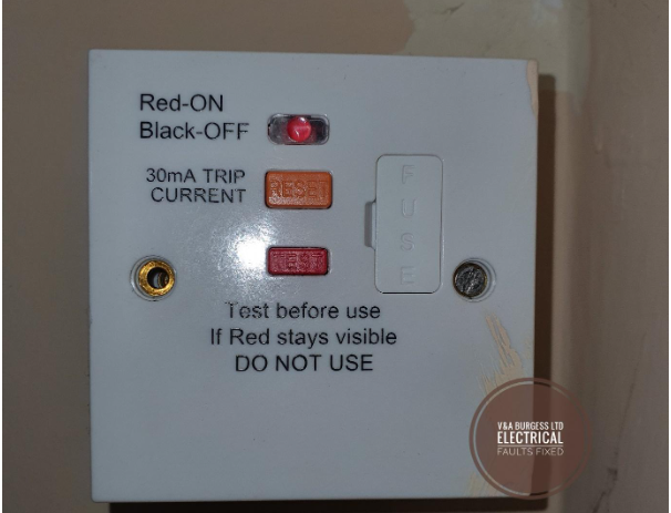
(PHOTO: A fused spur RCD switch that supplies a bathroom fan and light on the load wire)
Back to top3) What is a Load Conductor?
The load conductor is the wire responsible for delivering the power from the point of isolation or switching to the load connections on the electrical equipment. For example, a fused switch supplying an electrical boiler will have LINE CONDUCTORS delivering the power supply TO the switch where the LOAD conductors will then take over and deliver the power TO the appliance or equipment once the switch has been turned on.
Load conductors are all around us and can sometimes be referred to as a "switched live" meaning that load wires or load conductors are only LIVE when the switch is in the ON position.
Back to top4) Differences between Line and Load Conductors
Fundamentally LINE and LOAD conductors perform the same task, they allow the flow of electrical current through to equipment and appliances. There can be some distinct differences though. The table below may explain things better.
| Type Of Conductor | Cable Size | Purpose | Identification Colour |
| Line | Generally Constant Through the Circuit | Carries power from the panel / fuse box to electrical outlets | Generally Brown (UK and EU), Red (UK), or Black, Red (USA) |
| Load | Can be thinner than Line conductors in many cases | Takes power from switches and isolators to equipment | Generally Brown (UK and EU), Red (UK) or Black, Red (USA) |
| Neutral | Generally, the same size as the Line Conductor | Completes the electrical circuit returning current to the source | Blue (EU), Blue, Black (UK), White (USA) |
| Ground, Earth, CPC | A little smaller in some cases than the Line and Neutral | To connect metal or conductive parts of the electrical system to earth. Safety. | Green or Green Yellow (UK, EU, and USA) |
Back to top
5) Installation and Identification of Conductors
As an electrician and electrical tutor, I can safely say that electrical installation should be left to experienced professional electricians but identification of conductors should be easy enough right? The truth is, no matter what colour the wire MAY be, it does not mean that the wire is ACTUALLY what you think it is. I have seen many examples where ground wires have been used as a switched line or load conductor, neutral wires have been mis wired and are actually an earth conductor and all manner of things in between.
In order to correctly identify electrical conductors, some electrical test equipment may be necessary. A set of probes from a multi meter set to AC voltage should identify the incoming load wire when placed on the load terminals of any switch or isolator. Similarly, when checking for the line conductor, placing probes on the load terminals of the device and switching on and off will not only confirm the presence of load wires but that the switching point is working correctly.
Back to top6) Safety Implications of Incorrect Wiring
An electrical circuit can contain different colors of wiring dependant upon the type of circuit and not every color will make sense to the average DIY enthusiast. ALL wires should be assumed to be live, containing a dangerous voltage and creating safety concerns. The ONLY way to establish which wire is which is to TEST and prove if voltage exists.
A non-contact voltage tester (or volt pen) is completely insufficient in establishing if there are dangerous voltages present and should only be used to determine if there MAY be voltage present. The correct device for checking for voltages and proving dead is an approved voltage indicator to GS38 or USA equivalent standards.
Where wiring is carried out incorrectly, serious danger can exist. Wiring the load side into the line side of a switch for example will mean that the equipment will always have an electrical supply to it even when the switch is turned off!!
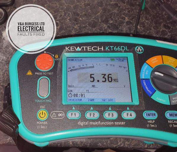
(PHOTO: Typical electricians test equipment to ensure that wiring is carried out correctly)
Back to top7) Lighting Circuits and Wiring
In the UK, lighting circuits can have yellow, blue, red, black, grey, and brown conductors. All of these can be LIVE conductors and should be treated as such. The reason for this is that they will all become a "switched live" or "load" conductor at some point during the operation of light switches. Black wires can be confused with a neutral wire when in fact, they may be a switched live on a lighting circuit.
Many a DIY enthusiast comes unstuck when dealing with an electrical project involving lighting installation or electrical repairs on a lighting circuit as there can be an awful lot of unexpected wires with no clear sign of identification! For this reason, residential wiring is often at more risk of electrical shock and electrical problems than other electrical installations.
Back to top8) What can we connect to the Load wire?
Electrical devices should be connected to the load wire on fused switches and isolators. Such equipment can include light bulbs, socket outlets not forming part of the main electrical circuit (extensions of the main circuit that are fused down by a switch), immersion heaters, gas boilers and more. It’s important to consider the fuse size and cable size to ensure that neither will be overloaded when connecting additional equipment to load wires.
Close attention is needed to ensure that the line terminals and load terminals do not exceed their capacity. Cables need to be selected to handle the electrical power that will be demanded of them. A professional electrician will design a circuit using the correct capacity electrical wires to ensure that no overload occurs.
Back to top9) What is connected to the Line wire?
The line connection will usually start at the electrical panel / consumer unit/fuse box and run to each point on the electrical circuit feeding electrical loads as it goes. In the case of lighting circuits, the circuit begins at the fuse box and continues until it reaches the end of the circuit forming a single "leg" or radial circuit. In the case of a ring final circuit (UK sockets) there will be a continuous loop of cable that has an incoming wires to the consumer unit and outgoing wires from the consumer unit forming the ring.
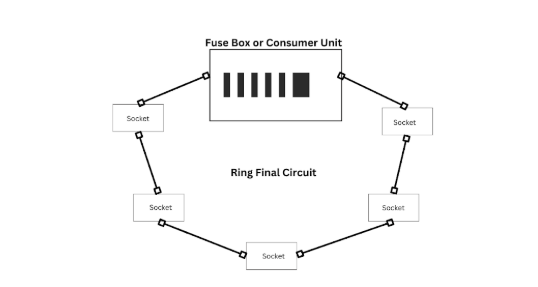
(Diagram: Ring Final Circuit for Plug Socket Outlets)
10) What circuit breaker is needed for each load?
Circuit design is undertaken with consideration for the types of loads that will be placed on the circuit. Electrical cables are selected based upon the design current of the circuit, a circuit breaker, fuse or other type of overcurrent protective device is then selected then various factors are taken into consideration such as ambient temperatures, thermal insulation issues and grouping of circuits in close proximity.
Generally speaking,
- Lighting circuits will not require more than a 6-amp MCB (Miniature Circuit Breaker)
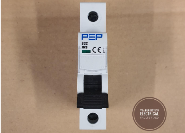
- Plug Sockets will require between a 16 amp and a 32-amp MCB
Electrical showers normally require at least a 32-amp MCB up to a 50-amp MCB dependent upon the rating of the shower.
11) Summary
Load and line wires both carry power to electrical equipment but the line conductors are the main part of the electrical circuit whilst load wires are there to carry the power to the final piece of equipment or electrical device. Different types of wires may be needed for the load wires and should be selected according to each of the various devices that requires a power supply. Electrical safety is paramount and careful circuit design is needed to meet the standards of the national electrical code or BS7671 wiring regulations. Before considering electrical work, ask if you can meet the standards of the wiring codes in your area? Do you have the correct test equipment and knowledge of its use? Professional help is the best way of achieving a safe electrical installation and a professional electrician should be used under most circumstances.
Back to top
Read more articles
- Log in to post comments

