
When commissioning a new electrical installation there are a variety of electrical tests that need to be carried out during the initial verification. Each electrical circuit must be fully tested during the testing process following the correct sequence of tests.
Test equipment or test instruments must be used to carry out the electrical testing. Such equipment must be checked for accuracy either through regular calibration or self-measurements on known markers to ensure no deviation of results over time.
When testing new installations of electrical systems prior to putting into service, dead tests must be carried out first in order to ensure that any subsequent live testing is safe to carry out.
Back to top1) Order of Electrical Testing
The correct order of electrical tests is as follows:
1.1) Dead Testing
- Continuity of Protective Conductors and Bonding Conductors
- Ring Final Circuit Continuity (If applicable)
- Insulation Resistance
- Polarity
1.2) Live Testing
- Polarity (Incoming Supply)
- External Earth Fault Loop Impedance (Ze)
- Prospective Earth Fault Current
- Prospective Short Circuit Current
- Earth Fault Loop Impedance (Total) (Zs)
- RCD testing
- Functional Testing
2) Dead Testing
2.1) Continuity of Protective Conductors and Bonding Conductors
An earth continuity test is vital for all circuits to ensure that there is a circuit protective conductor (CPC) at every point on the circuit. Electrical circuits will function in many cases without a circuit protective conductor but the absence will mean that potential danger exists. The sufficiency of any bonding connections will also be checked at this time to ensure that extraneous conductive parts do not introduce a dangerous earth potential during fault conditions.
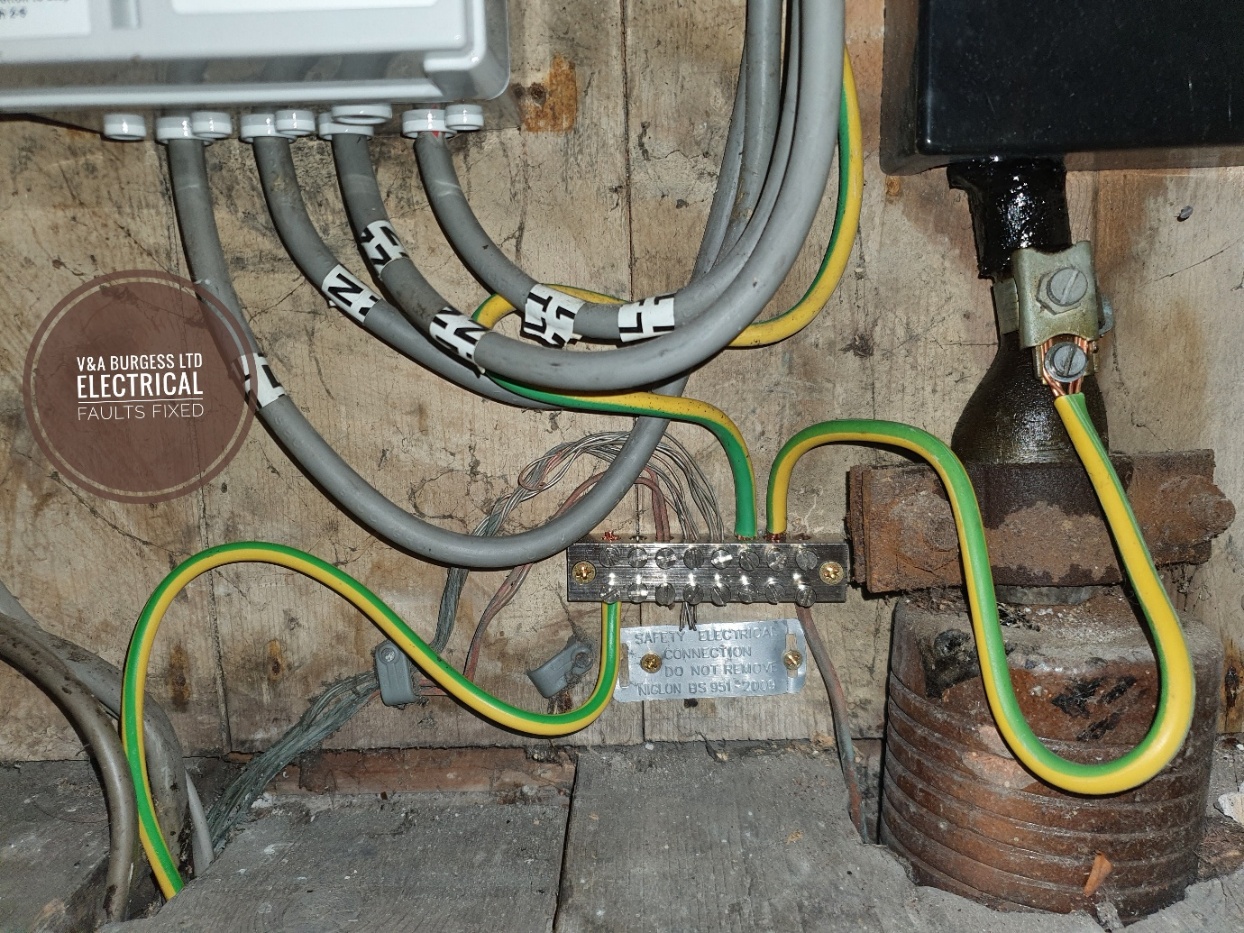
(Photo: Main Earthing Terminal incorporating Bonding Connections)
At this time, it is important to not only check R1 (Line Conductor) and R2(circuit protective conductor) values but also Rn (neutral conductor) continuity on all circuits. This will also confirm polarity. Continuity testing is the vital first step of the test procedure and like the other tests, further test cannot be completed without successful results on this test.
2.2) Ring Final Circuit Continuity
In the UK, it was commonplace to install a Ring Final Circuit for socket outlets. This is occasionally still the case today (2025) although many electricians are favouring radial circuits instead of ring final circuits for socket outlet installations. There are special testing requirements for Ring Final Circuits to ensure that safety measures are met.
End to End Testing
Each of the three conductors used in a ring final circuit will be checked for continuity to ensure that the integrity of the ring is maintained. A low resistance ohmmeter or multi-function tester is used for this process.
Crossover Tests
Once each conductor has been verified as continuous, the test procedures move to the "crossover" or "figure of 8" testing.
This crossover test involves connecting the Line conductor of each leg with the CPC of the opposite leg to form a continuous loop of cable or "figure of 8". The measured resistance at each socket outlet is then checked against the calculated values to ensure that there are no loose connections or other issues. This test also goes half way to proving dead polarity for the ring final circuit.
The crossover test is repeated for the Line and Neutral conductors, and assuming expected values are obtained at each socket outlet, this fully confirms polarity of each of the outlets and the circuit.
2.3) Insulation Resistance Testing
During the process of insulation resistance testing, we are checking for unwanted connections between conductors such as earth faults and short circuits. The test instrument applies a voltage between each of the conductors and the insulation resistance reading is measured. We are checking the quality of the insulation on the cabling, the accessories and throughout the electrical circuits.
The readings obtained should be in Mega Ohms (Millions of Ohms) and be at least 20M Ohms in a new installation. A value less than this, may require some investigation.
2.4) Polarity
The polarity test is often not a separate test. During dead testing we will be able to visually confirm polarity on lighting circuits and most other radial circuits. Readings are often obtained at the terminals of equipment where it can be seen that each conductor is correctly inserted into each terminal.
Back to top3) Before Energising
Once all dead tests have been successfully completed, we are able to energise the installation to carry out live testing. It is important not to proceed from one test to another without each dead test in order being completely successful. Proceeding on to insulation resistance testing without confirming continuity of conductors (for instance) may mean that insulation resistance is meaningless. If we think about it, we cannot insulation test a whole circuit if we have not confirmed that the circuit is continuous!!
Back to top4) Live Tests
4.1) Polarity Incoming Supply
The incoming mains supply is checked to ensure that the correct conductors are inserted into the correct terminals. The voltage across each of the conductors is also checked using an approved voltage indicator to ensure that there are no faults external to the installation with polarity.
4.2) External Earth Fault Loop Impedance (External) Ze
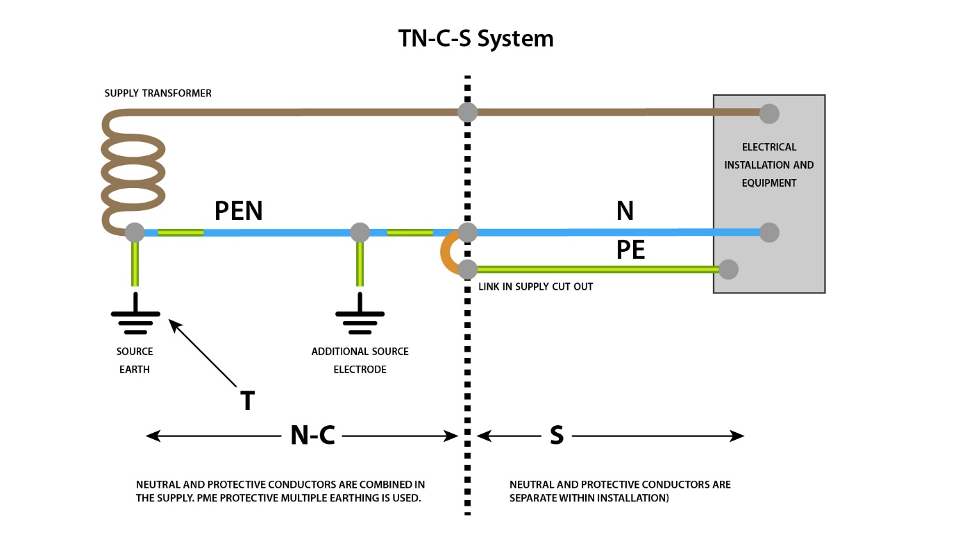
The resistance of the earth fault path back to the supply transformer is checked to ensure that the values for our earthing system are within the expected range. These are: TNCS - 0.35 Ohms
TNS - 0.8 Ohms
TT - As low as possible but under 200 Ohms
The earth fault path involves checking the resistance of the Line and Earth conductor. The specific purpose of this test is to ensure that our disconnection times can be met for our overcurrent protective devices.
4.3) Prospective Earth Fault Current
This type of test examines the maximum fault current that could be generated at the point of measurement. This helps with selection of protective devices and other switchgear to ensure that, should a fault develop, the breaking capacity of such devices could handle a fault. All earthing and bonding connections should be present and continuous for this test as this represents the lowest possible resistance and worst case scenario for fault current.
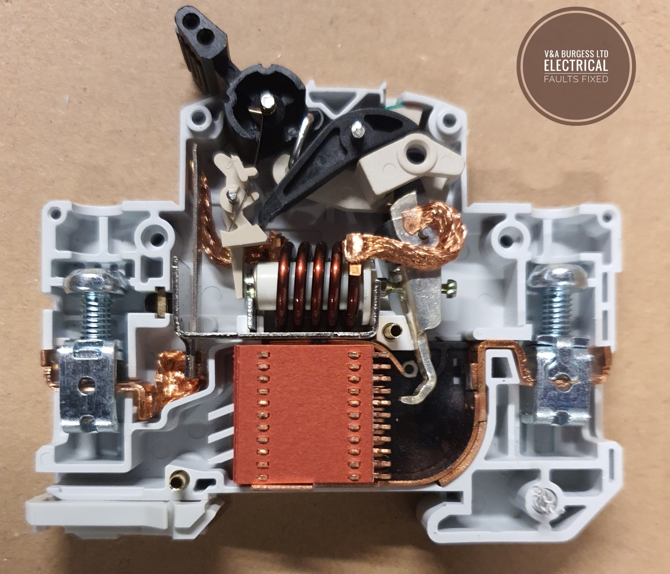
(Photo: Inside a Circuit Breaker)
4.4) Prospective Short Circuit Current
The short circuit current test on the electrical supply must also be checked as in some earthing systems, this fault current can exceed the earth fault current. Electrical devices can be selected based on the results of this test to ensure that there are no potential problems with breaking capacity on consumer unit equipment.
4.5) Earth Fault Loop Impedance (System) Zs
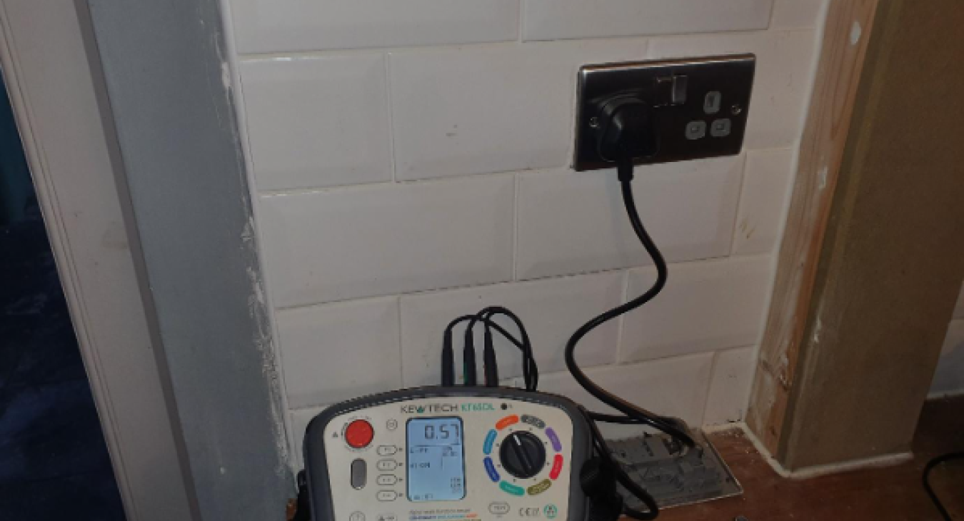
The next steps, following successful previous tests, are to check the total earth fault loop impedance for each circuit or calculate it. Where it is safe to do so and not in breach of live working regulations (EAWR 1989), Zs can be measured. In practice this means using an appropriate test instrument at each socket outlet and calculating the other results to help eliminate the potential risks of live working such as electrical shocks.
4.6) RCD testing
The Residual Current Devices should be checked to ensure their correct operation, after all, they are one of the most important measures in protecting against electric shocks. The devices should be tested using a suitable RCD tester or Multi-Function Tester in accordance with the latest version of BS7671. Once the correct trip times have been confirmed, the RCD test button should be pushed to ensure it trips the device.
4.7) Functional Testing
Each switch throughout the property should be checked to ensure that its function is carried out. This includes light switches, socket outlet switches, pull cord switches, switchgear in the consumer unit such as MCBs, RCBOs and Main Switch.
Back to top5) Finally
Once all testing has been carried out and results confirmed, the results should be documented on the correct form. For a periodic electrical inspection this is an Electrical Installation Condition Report and for new electrical installations this is an Electrical Installation Certificate.
Only a professional electrician or competent person should carry out electrical testing as they are trained to understand the wiring regulations, test procedure and interpret the results correctly. Working with electrical equipment requires knowledge, training, and experience to ensure danger is minimized. The specific sequence should be followed throughout the testing procedure.
Back to top6) Periodic Inspections and Testing Procedure
The testing procedure for periodic inspections can be carried out in a different manner and need not include all of the tests. If successful test results are not obtained on one test, then subsequent tests may not be accurate but a full inspection is often not possible or practicable on a periodic inspection.
Back to top
Read more articles
- Log in to post comments
